
Line-scan is a powerful yet underutilized computer vision technique. This article introduces the concept and applications of line-scan, reviews timing issues and considers image processing approaches.
Line-Scan concept and applications
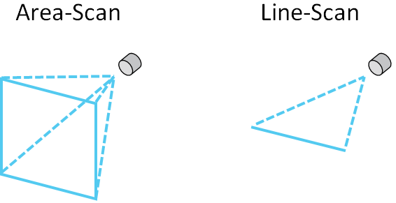
Most cameras used in industrial computer vision are area-scan, meaning the camera captures a 2-dimensional array of pixels in a single exposure. For example, a typical area-scan resolution is 640 x 480 pixels, capturing an image composed of 480 rows of 640 pixels each. Line-scan cameras capture a single row of pixels per exposure. A typical line-scan resolution is 2048 x 1 pixels, capturing one row of 2048 pixels. As an object moves across the line-scan camera’s beam, successive single-row scans are taken which are stacked together to form a complete image of the object. The object under inspection therefore needs to be moving relative to the camera in order to create a full image using line-scan.
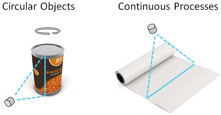
Line-scan is applicable in two main scenarios. The first is when inspecting objects which are difficult to capture with area-scan due to their shape or size. An example of this is circular objects, which can be rotated in front of a line-scan camera to create a flattened image. Similarly, large objects such as a glass window pane can be moved across a line-scan beam to create a complete image of the object, otherwise impossible to capture using area-scan. The second scenario is when inspecting continuous processes such as paper being fed through rollers in a pulp & paper mill.
A significant advantage of line-scan over area-scan, especially when inspecting large objects, is less optical distortion. Barrel distortion is a common problem when attempting to capture a large object using area-scan. As line-scan operates in one dimension only, optical distortion can be more easily addressed. The other key advantage of line-scan is its ability to capture objects moving at high speed. Area-scan cameras can suffer from blurring when capturing fast-moving objects. Due to its one-dimensional nature, line-scan cameras can operate with very short exposure times, allowing clean capture of objects even when moving at speed.
Timing considerations
As line-scan cameras build a line-by-line image of a moving object, synchronization is required between the movement of the object and the camera scans. Poor synchronization leads to lines being stretched or compressed relative to one another, generating a distorted image. Note that this is very different to optical distortion such as barrel and pincushion effects. The result is a change in pixel aspect ratio, which can affect the performance of defect detection algorithms.

Timing synchronization is addressed by one of two means. The first and most common approach is to use an encoder to detect the motion of the object and send this information to the camera. In a conveyor system for example, a rotary encoder detects the rotation of the conveyor’s driving spools and generates a calibrated number of pulses per degree of spool rotation, indicating the linear movement of the conveyor surface. The line-scan camera receives the encoder pulses and uses them to trigger the scanning of each line, ensuring a constant pixel to distance ratio. The second means of achieving timing synchronization is using a simple timer in the camera which scans new lines at a constant frequency. This solution is simpler than using an encoder however it is only applicable when the speed of the moving object is absolutely constant. This is rarely possible in practice as automated conveyor speeds vary when different loads are applied.
If line height stretching and compressing is observed when using an encoder, the root cause is often slippage. Objects can slip on conveyor belts and conveyor belt surfaces can slip relative to the driving spools.
Image processing considerations
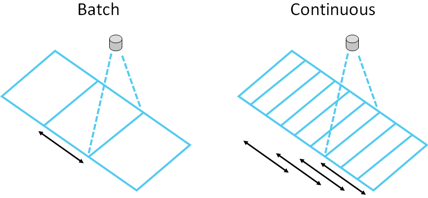
There are two approaches to processing line-scan images. The ‘batch’ approach assembles individually-scanned lines into rectangular images and processes them in one go as a batch. Each individual line is processed only once as part of its batch. The next batch of lines starts where the previous batch ends. The alternative, the ‘continuous’ approach, can be considered as a rolling series of overlapping batches. Each individual line is processed multiple times, depending on the number of lines per batch and the batch frequency. The danger of the pure batch approach is that defects can be cut in half between batches and potentially not detected. This issue is addressed by the continuous approach, with the consideration that additional image processing capability is required to handle the extra load.
Conclusion
Line-scan vision systems provide a powerful solution when inspecting large, circular or continuous objects at high speed. Line-scan systems are more robust to optical distortion however timing distortion can be a challenge, especially when object or conveyor slippage occurs. Batch processing is simple and light on computational resources but continuous processing should be considered when defects need to be assessed in their entirety.