
When GigE Vision and USB3 Vision communication protocols entered the computer vision market, enabling cameras to be connected to regular PC communication ports, people thought it was the end of the frame grabber. Despite the introduction of these more ‘plug and play’ communication protocols, the frame grabber continues to play an important role. This article explores the role of the frame grabber in modern computer vision and describes how to integrate frame grabbers into vision applications.
The role of the frame grabber
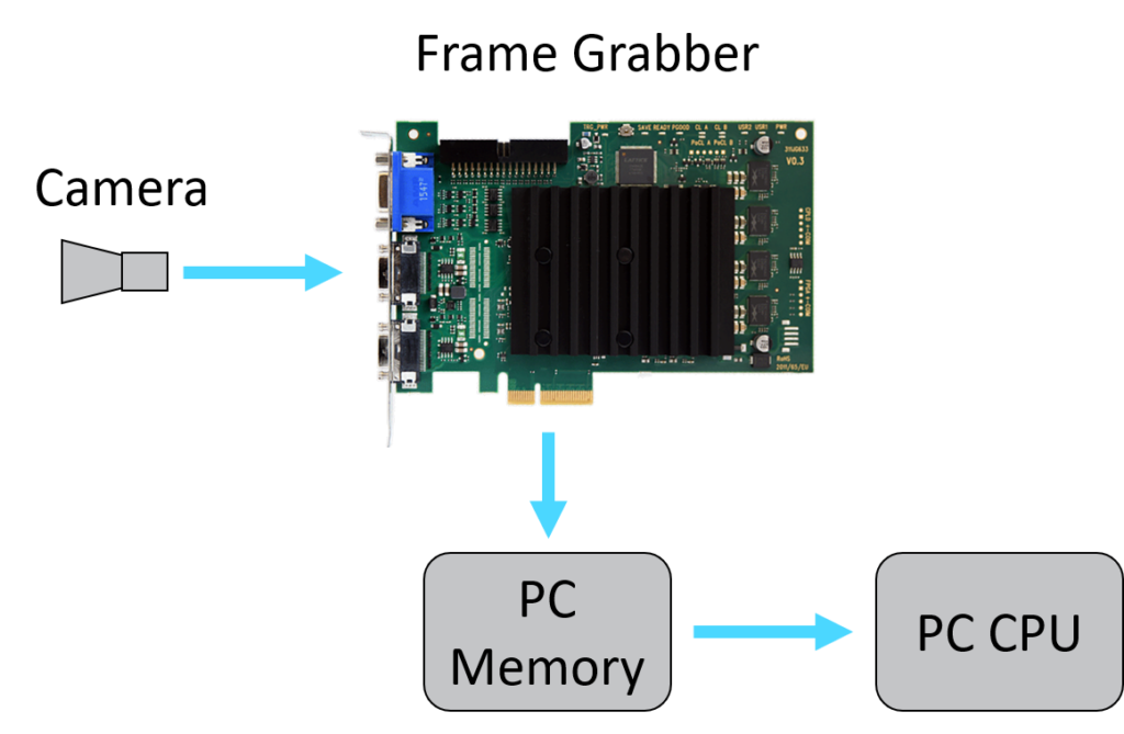
Frame grabbers were originally developed in the early days of computer vision when cameras produced analog signals which were processed by low power digital computers. A device was needed to convert the camera’s analog signal to a digital format and place the image directly on a data bus for the computer’s CPU to access. Even when cameras became digital, a device was still needed to manage the incoming data stream from the camera and feed it into the computer’s memory. This need was met with a frame grabber – a card which plugs directly into the computer’s motherboard, typically into a PCIe slot, and provides a physical input socket for the camera.
Even as PCs became more powerful, and more able to handle incoming camera data directly, vision-specific communication protocols prolonged the role of the frame grabber. Protocols such as Camera Link, a long standing workhorse of high speed computer vision, are not directly supported by PCs – dedicated hardware and drivers are required. The more recent application of standard communication protocols to computer vision, notably Ethernet and USB in the form of GigE Vision and USB3 Vision respectively, has allowed direct camera to PC connections, potentially eliminating the need for frame grabbers. There remain however two key scenarios where frame grabbers are still necessary:
- Applications with very high data rates can exceed the limits of GigE and USB3, necessitating a high speed protocol such as Camera Link or CoaXPress for which a frame grabber is required. GigE Vision is theoretically capable of 1000 Mbit/s (125 MB/s) although this is usually limited to 800 Mbit/s in practice due to communication overheads. USB3 Vision is based on the USB 3.0 specification, giving 3.2 Gbit/s (400 MB/s). Camera Link and CoaXPress can achieve 6.8 Gbit/s (850 MB/s) and 12.5 Gbit/s (1562 MB/s) respectively.
- Even when GigE or USB3 are capable of transferring camera data at the required speed, the PC’s CPU may not be able to handle the acquisition and processing in a timely manner, especially in multi-camera architectures. A frame grabber provides a means of off-loading a portion of the work and placing pre-processed image data directly in the PC’s memory. This option is becoming more attractive as frame grabber manufacturers increasingly offer programmable FPGA solutions which are capable of handling complex image processing workloads.
Working with frame grabbers
To illustrate how frame grabbers are integrated into vision systems we’ll make reference to the tools available from Silicon Software, which are typical of those available from all frame grabber manufacturers. Silicon Software is located in Germany and specializes in FPGA-based frame grabbers for Camera Link, CoaXPress and GigE.
Once a new frame grabber is correctly installed on the PC’s motherboard, the first task is to flash it with the appropriate firmware. Frame grabber manufacturers usually provide a variety of firmware files to cater for different application requirements, for example area scan, line scan, colour and monochrome. Silicon Software provides a desktop application called microDiagnostics which identifies the frame grabbers installed on the PC and guides the user through the firmware flashing process.
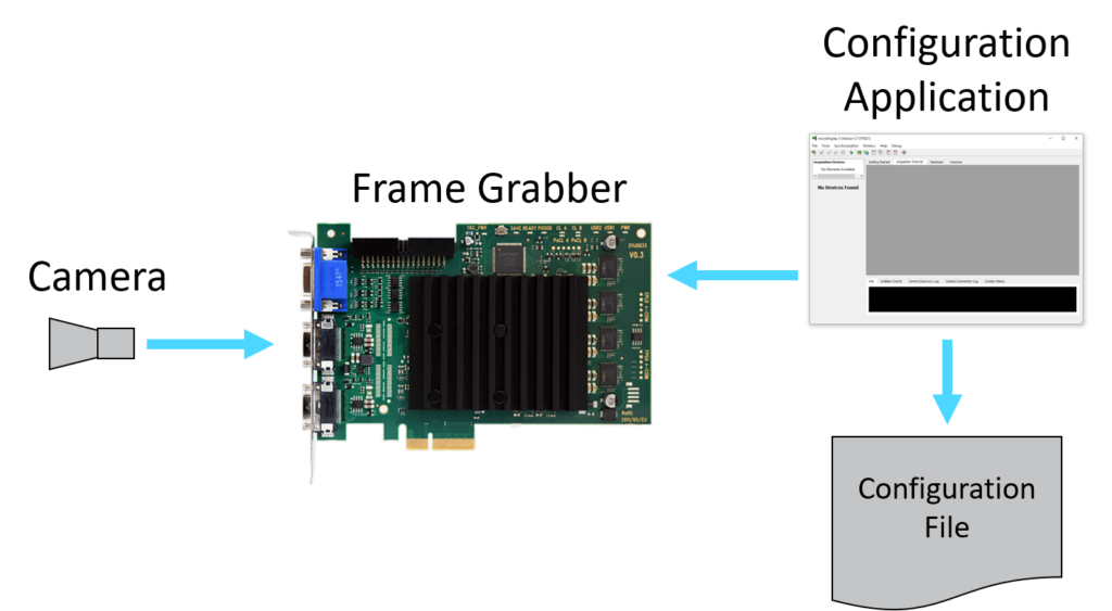
Having flashed the frame grabber with the correct firmware, the vision engineer’s main task is to configure and program the frame grabber’s firmware for the needs of the application. Most frame grabbers are configurable but not programmable. Configuration refers to changing settings such as ROI and encoder clock source. Programming refers to developing image processing algorithms on-board the frame grabber. Programmable frame grabbers are usually FPGA based and are approximately ten times more expensive than configurable frame grabbers. Let’s explore configuration in more detail, it being the more common workflow: frame grabber manufacturers usually provide a desktop application for changing configuration settings, which can be saved in a configuration file. In the case of Silicon Software, the microDisplayX application is installed on the host PC and allows the user to experiment with configuration settings.
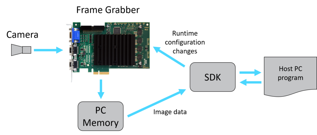
Once the configuration settings have been determined, the next step is to explore the frame grabber’s SDK (Software Development Kit). A frame grabber’s SDK provides us with an API (Application Programming Interface) to use in the vision application on the host PC. In the case of Silicon Software, the SDK is written in C/C++ with wrappers in C# and Python. The main objective of the SDK is to provide functions for accessing image data at runtime, which the frame grabber places directly in the host PC’s memory, and to change runtime configuration settings via the application code.
Once an image has been accessed via the SDK, it can be processed in the host PC program with any image processing library such as Cognex VisionPro, Matrox MIL or MVTec Halcon.
Conclusion
Despite the introduction of GigE Vision and USB3 Vision, enabling direct camera to PC connections, the frame grabber still has an important role to play in vision applications which have high data rates and/or require considerable image processing.